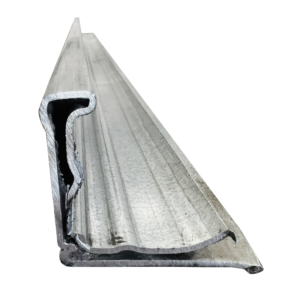
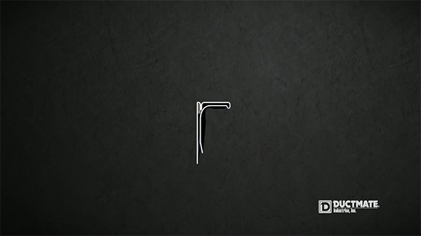
Step 1. Cutting—Flange to required lengths
-
- Cut with a non abrasive saw and with the legs facing down so that no metal chips get into the mastic filled sleeve.
-
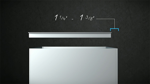
- Cut Flange 1-1/4” to 1-3/8” shorter than the raw edge of the duct wall it’s sliding over.
Components Used in Step 1:
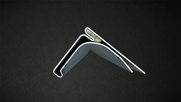
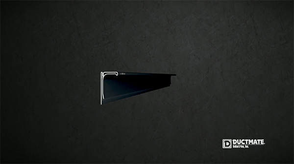
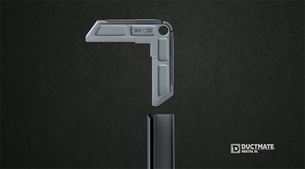
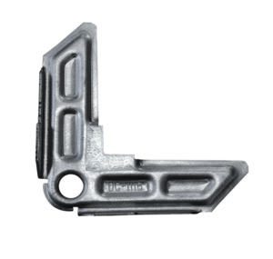
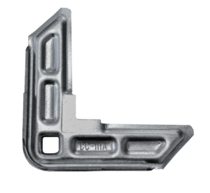
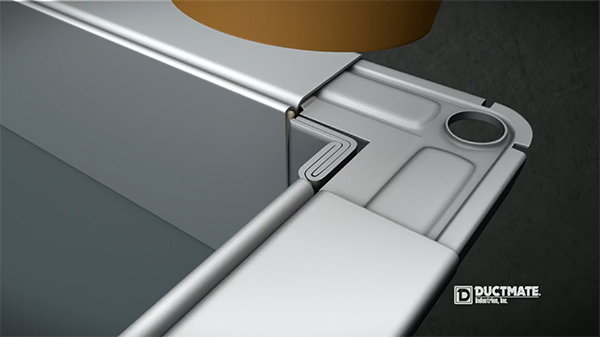
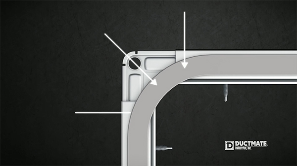
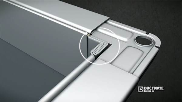
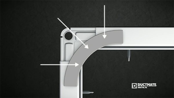
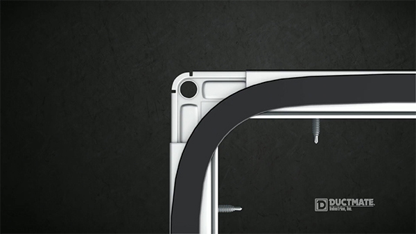
Step 2. Assembling—Corners into Flange to form a Frame
The Frame consists of two main parts: the Ductmate Flange and corner
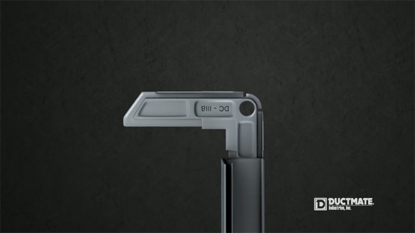
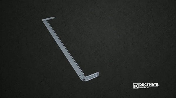
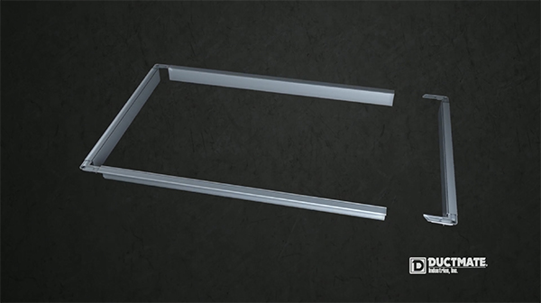
Components Used in Step 2:
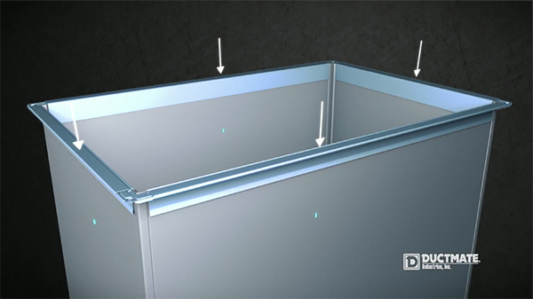
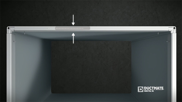
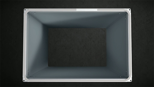
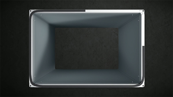
Step 3. Fastening (Part 1)—Slide On and Seat the Frame to duct work
-
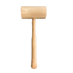
- With a Wood Mallet hammer the frame onto the 4 raw edges of the Rectangular Duct.
-
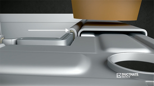
- Seat the frame down on the duct wall so that the raw edge of the duct wall is flush with the top of the Ductmate sleeve which has an integrated mastic.
Components Used in Step 3:
Step 4. Fastening (Part 2)—Securing Frame to Duct Wall
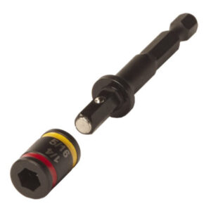
We suggest the #10 x ¾” High Hat simply because it holds better in the Drill Chuck than the short head on a standard #10 x ¾” Drill Screw
Components Used in Step 4:
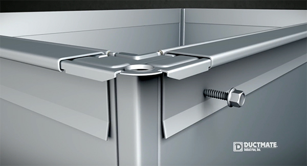
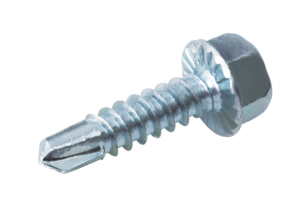
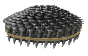
There are three options for fastening the flange through the duct wall.
A. Drill Screws
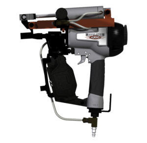
B. Ductmate Repeater Nails
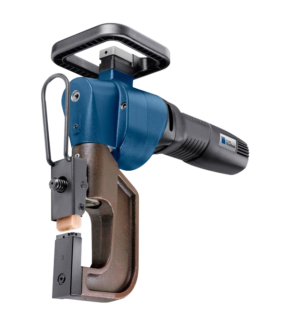
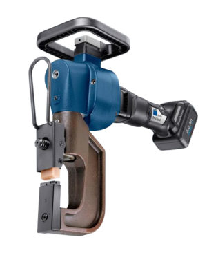
C. Clinching using a Trumpf 350 Power Fastener
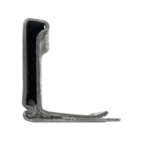
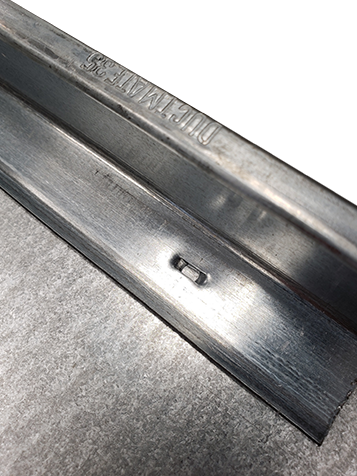
-
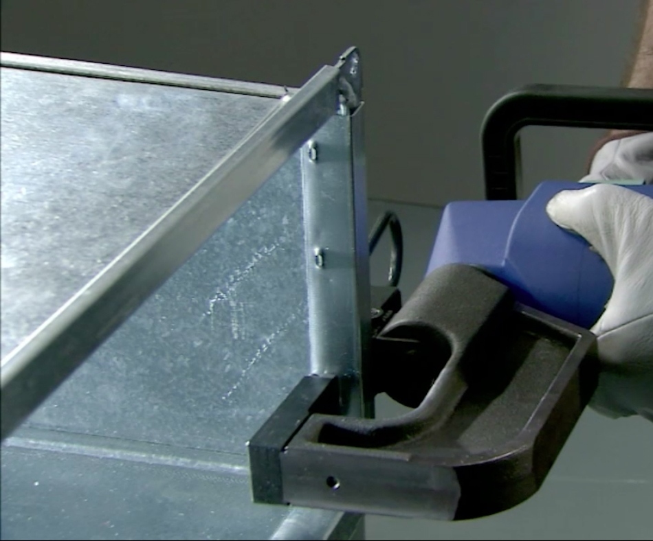
- Inside view of clinch
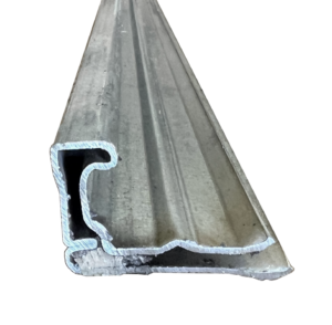
-
- DM35FL Fastened with Trumpf TF350
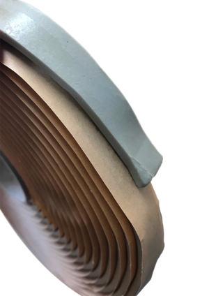
Step 5. Gasketing—Two Duct Sections
At this stage, the work moves to the job site 90% of the time
The first step is applying the Butyl Gasketing. Only one of the two mating sections is completely Gasketed around the face of the flange. The second section is Gasketed only at the four corners.
-
- Start about mid point of one of the duct sides
-
- Extend around edge so gasket is applied in between corner and the raw edge of the duct work
-
- For example, this circled area needs to be Gasketed ( in this image it’s where the Pitts seam on the straight duct is joining with the Ductmate Frame and Corner)
-
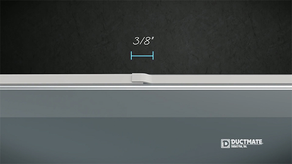
- Arriving back at the start point, overlap about 3/8” and press down firmly. That completes one section.
Components Used in Step 5:
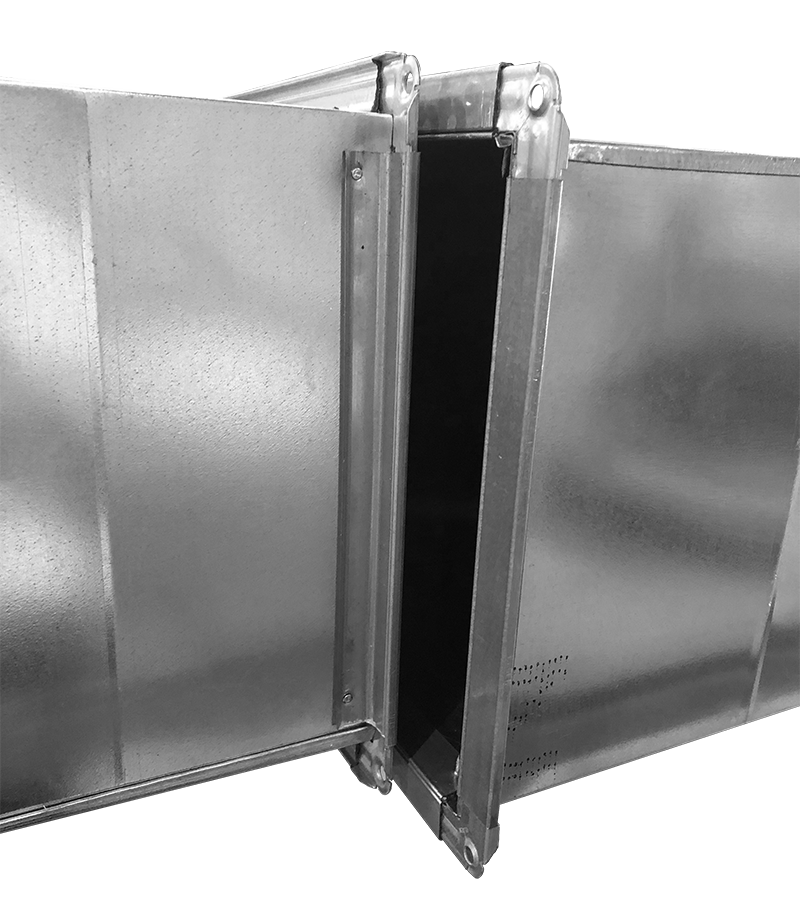
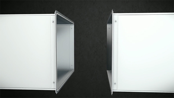
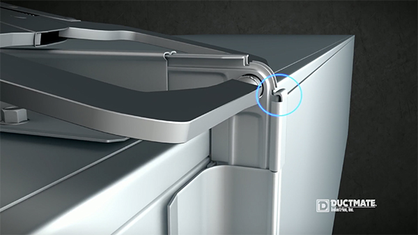
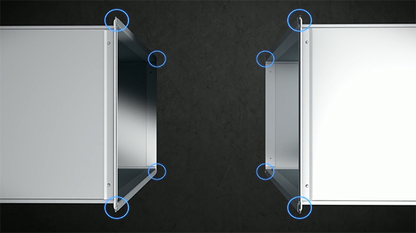
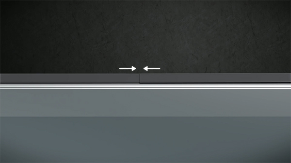
Step 6. Connecting
-
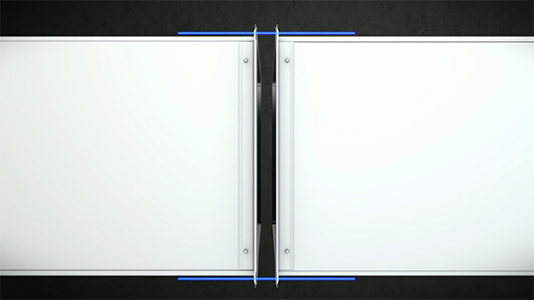
- It is important to make sure the duct is aligned before the Butyl Gasket touches the mating section as it’s challenging to take apart.
-
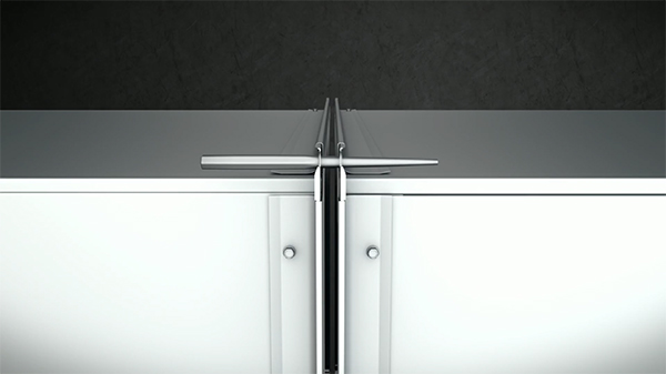
- A drift pin assists in this Alignment
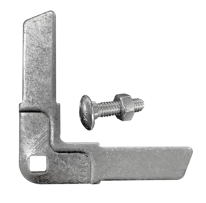
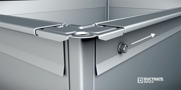
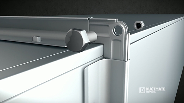
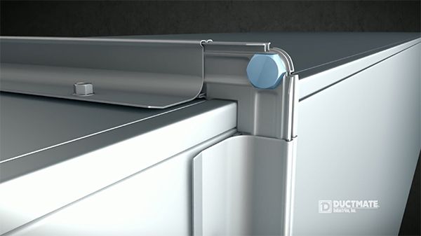
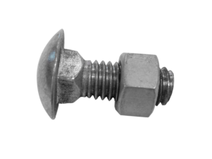
3B corners are often used for Bolt on despite their round hole. The recommended corner for Bolt-on is 3A which has a square hole and a continuous flange around the edge of the corner. The images below show the 3B Corner used as a Bolt On.
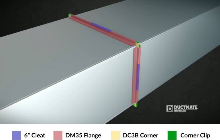
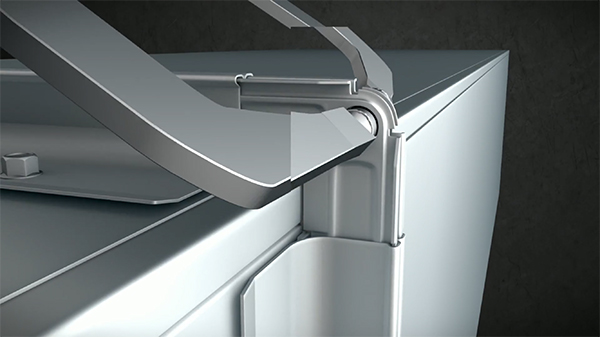
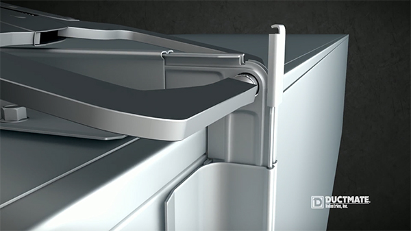
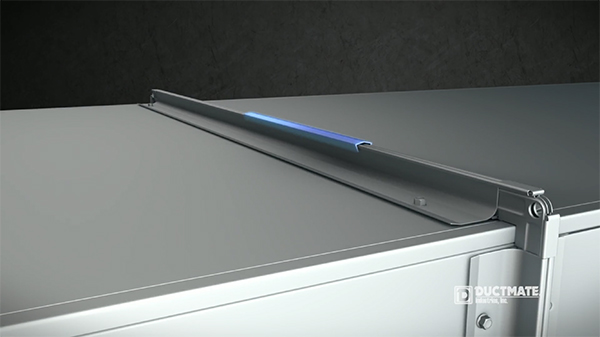
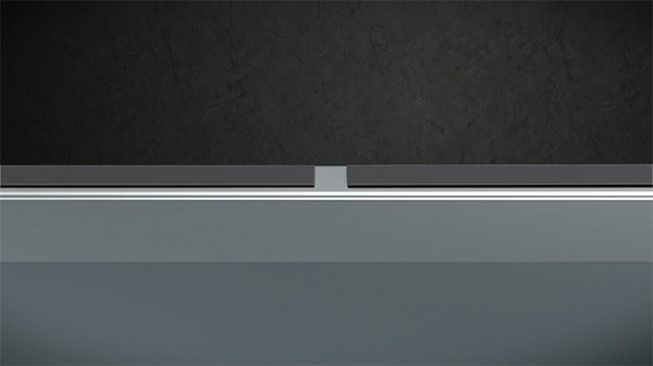
Securing the 4 connections with a 6” Cleat is the final step
-
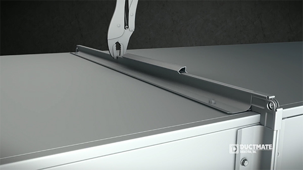
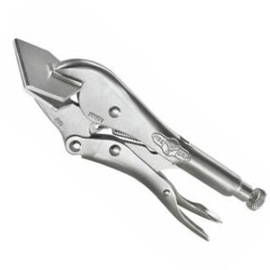
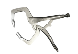
- Pull the two sections together, a task made easier with Vise Grips
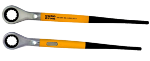
-
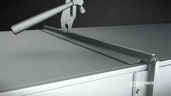
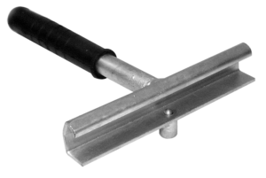
- Using a Tinners Hammer like the Duro Dyne TH18 Rubber Grip, hammer the flat top of the 6” Cleat to cleat over each frame. Note: image shows the Versa Cleat which has a Pyramidal top. Best to use a Cleater tool on these
Components Used in Step 6:
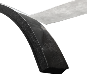
Not all jobs are suited for Butyl Gasketing…
Some Rectangular Duct connection applications will call for Neoprene Gasketing instead of Butyl. Neoprene Gasket allows for easier separation and alignment, better for inspection or cleaning. We have a few contractors who use the Neoprene for PreFab work in which they want to do the Test & Balance at shop rather than on job site. (Butyl Gasket is like gum, it would not pull apart without major effort and mess).
When applying Neoprene Gasket, the “prep” is more important. Clean the face of the Flange and then seal /caulk all 8 corner edges.
-
- Follow the same pattern as Butyl application
-
- Except instead of overlapping material, butt the edges
Components Used: